Study: Optimal Placement of Negative Pressure Ventilation Pipes on a Low-pitched Roof
A simulation conducted by Ramboll Finland Oy explored the optimal placement of negative pressure ventilation pipes on the low-pitched roof of a box-shaped building. The study found that airflow is not evenly distributed across the roof: the greatest pressure differences and flow velocities typically concentrate near the center of the roof, while the edges have significantly less airflow. This means it is more effective to place relatively more ventilation pipes at the center of a low-pitched roof than near the edges.
Roof structure ventilation methods vary. Sometimes a building has a “hot roof”, meaning it is a non-vented attic system. It is also possible to ventilate the roof structure with passive ventilation where ventilation grooves allow for the air to flow in structures.
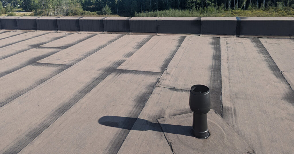
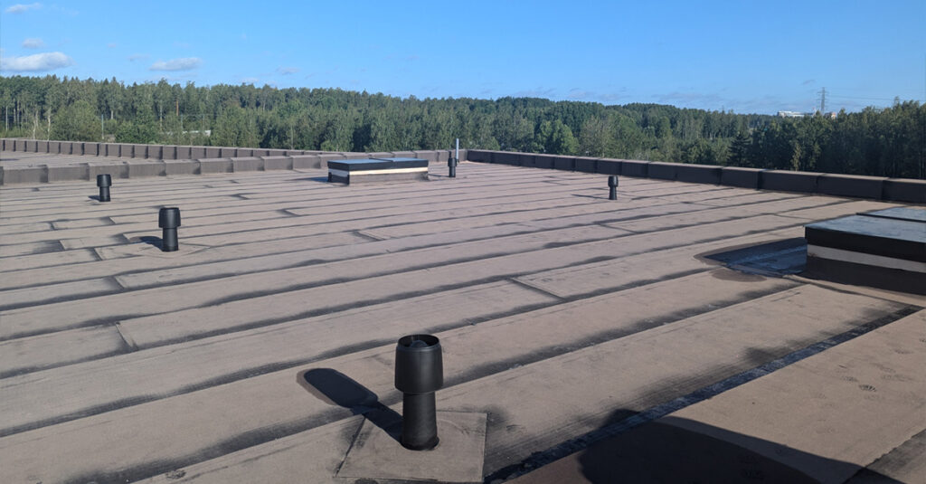
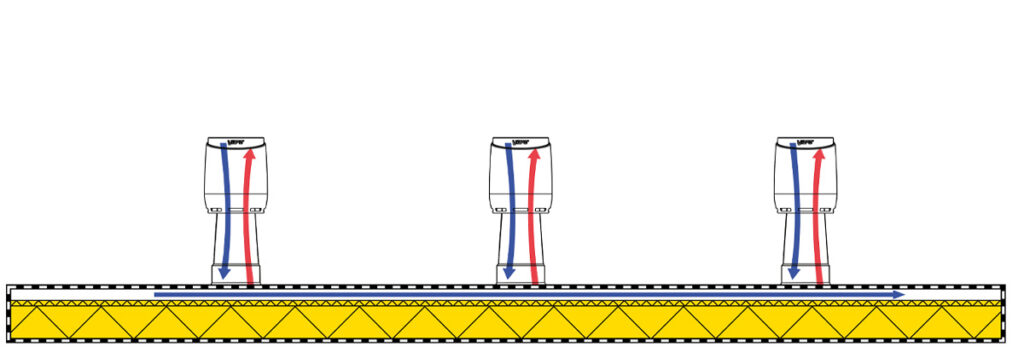
For example, in Finland, passive ventilation has long been used to safeguard the health of roof structures. Passive ventilators, together with wind flow, create a negative pressure within the roof structure, which promotes air exchange and removes humidity from the insulation layers. As wind passes over a negative pressure ventilation pipe, it creates suction that draws air and humidity out of the structure, helping to prevent potential moisture damage.
Traditional passive ventilation depends entirely on weather and wind conditions (with an air exchange rate of 20–40 changes per hour), whereas modern mechanical ventilation systems equipped with roof fans can achieve up to 140 air changes per hour with demand-based control. Simulations involving leaks have shown that passive ventilation can dry out structures within three years (link to article). Typically, a system with multiple negative pressure ventilation pipes is used on the roof to ensure optimal performance.
Placement of Negative Pressure Ventilation Pipes: Research Background and Implementation
Although a great deal is known about the drying capabilities of passive negative pressure ventilation, relatively little data exists on how wind flows across low-pitched roofs and how this affects ventilation efficiency. To address this, a study was commissioned to analyze airflow variations and determine the optimal placement of negative pressure ventilation pipes on a low-pitched roof, so they function effectively under different weather conditions. The study was conducted using Computational Fluid Dynamics (CFD) simulation, prepared by Mats Böök from Ramboll Finland Oy.
Key aspects of the modeling:
- Eight different wind directions (every 45°)
- Vertical wind profile with a base speed of 5 m/s
- Target building: box-shaped industrial building (21.6 m × 81.6 m × 10 m)
- Software used: Engys HELYX 4.2.1
- Turbulence model: k-ε Realizable
- Isothermal assumption – no temperature difference modeling
- Surface roughness modeled after a semi-rural area with sparse tree cover but no dense forest
Results: Airflow is Uneven – Highest Efficiency at the Center
The simulation showed that airflow is not evenly distributed across the roof. The greatest pressure differences and flow velocities were found at the center of the roof. As a result, the best ventilation performance is achieved when negative pressure ventilation pipes are placed along the roof’s central width axis and about 10.5 meters from the roof edges along its length.
Key findings:
- Velocity distribution above the roof: Wind speed averages were analyzed at the height of the ventilation pipe on a horizontal cross-section. The most favorable flow conditions occurred in the center region.
- Symmetrical building shape: The nearly symmetrical form of the building led to similar results for all wind directions, emphasizing the importance of the central axis for ventilation pipe placement.
- Efficient airflow: Optimal locations were those with the highest airflow speeds, ensuring the best performance of the negative pressure ventilation pipes.
- Potential obstacles: If large structures like technical HVAC rooms for heat recovery ventilation units are placed in the center of the roof, wind conditions worsen. In such cases, more negative pressure ventilation pipes or mechanical solutions (e.g., the VILPE Sense system) may be required to compensate for reduced airflow.
It’s important to note that all buildings are unique, and this study only examined the roof of a box-shaped building. While the principles may partially apply to other building types, it is recommended to assess each site individually to optimize ventilation pipe placement according to the building’s specific characteristics.
Study Conclusions and Practical Application
Based on this study, the placement of negative pressure ventilation pipes significantly affects roof structure ventilation and humidity management. The CFD analysis made it possible to identify the best locations on the roof, enhancing ventilation efficiency under varying wind conditions.
- Enhanced ventilation: Ventilation is most efficient where pressure differences are greatest—typically in the center of the roof. Optimizing placement ensures sufficient airflow and helps avoid moisture damage.
- Fewer structural damages: Humidity is a major cause of structural deterioration. Effective humidity removal increases the building’s lifespan and reduces maintenance needs.
- More ventilation pipes in central areas: Since the center of the roof provides the greatest ventilation benefits, it often makes sense to install relatively more ventilation pipe there than on the edges.
- Impact of obstacles: Large structural elements (e.g., HVAC rooms) in the central area reduce wind flow. In such cases, a denser ventilation pipe layout or mechanical solutions should be considered.
- Wide applicability: These placement recommendations can be used in both new and existing industrial buildings. The core principles also apply to other building types where roof ventilation is critical.
Study Limitations
This study focused only on a box-shaped building with a low-slope roof, using an isothermal assumption, meaning temperature differences were not modeled. The surface roughness parameter represented a semi-rural environment with some trees but no dense forest. Because of these choices, the results should be seen as indicative only and not directly generalized to all buildings or conditions. Each project should be individually assessed to ensure accurate and reliable results.
Read more about automatic and demand-controlled roof ventilation
More information via email:
Katarina Hellén
katarina.hellen@vilpe.com